There’s a few ways to do this, I think the simplest, if you have the PCIE slot room would be to buy an ethernet card that supports 10/5/2.5/1GbE network speed negotiation.
But since I only have one real usable slot in my pfSense machine, and I need 10G for LAN, I opted for a dual-port Mellanox ConnectX-3 SFP card that I purchased off of eBay for $21 USD. An incredible buy. I would definitely recommend putting a fan on the heatsink if you have room, or blowing across the card is even better to help cool the SFP modules themselves. Especially when using ethernet modules, they run hotter than fiber modules.
Per the previous guide, I updated my /conf/dhcp6_att.conf to replace interface re0 with interface mlxen1 (by process of elimination or checking ifconfig to determine which slot is which. What the bracket of the card calls port 0 actually was my mlxen1 interface, in this case.
In pfSense, you will see it negotiate as 10Gbase-CX4. The speed of the port does not matter, assuming it supports your standard 1G/10G SFP+ port speeds. The module is what matters. The modules SFP end will interface with the port at 10Gbase-CX4, and the ethernet side of the module will interface with your modem at 5Gbase-T. You’ll have to login to your AT&T modem to confirm the speed of the client (under Device > Device List). Make sure you’re connected to the 5G port on the back of your AT&T BGW320!
As I only pay for the 1G plan, I am at least now able to pull the full speed.
I’ve spent the last few days making this work properly across multiple VLANs, because AT&T does NOT even REMOTELY conform to any kind of industry standard for dishing out IPv6 blocks or addresses.
Normally your WAN would receive a /56 block from an ISP, giving you 00-FF in blocks to assign off of that. And everything you read online says AT&T gives out a /60, which is true. But it’s misleading if you’re expecting to be able to USE that /60. You cannot. You cannot give your WAN adapter a /60 prefix, it does not work that way. It will always be a /64. (we’re not talking about a custom ONT SFP module here or what-not, obviously some people have made it work that way).
So, assuming you just want to use the AT&T BGW320 as-is, and you want multiple IPv6 prefixes, here’s my quick little guide on that.
On the BGW320:
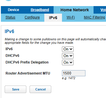
Turn all 3 settings to On under Home Network > IPv6
Under Firewall > Packet Filter, click to Disable Packet Filters (Note: This is not required for this guide, but you should just let pfSense handle packets if that’s your router)
Under Firewall > IP Passthrough – Allocation Mode: Passthrough – Passthrough Mode: DHCPS-fixed – Passthrough Fixed MAC Address: pfSense WAN adapter MAC address
Under Firewall > Firewall Advanced: I would recommend Reflexive ACL, ESP ALG, SIP ALG be turned Off.
pfSense Configuration
Under Interfaces > WAN – IPv6 Configuration Type: DHCP6
Note: If you only ever want 1 prefix to use for your LAN, and don’t plan to use any other /64 blocks, you do not have to use a custom configuration and could essentially stop here. Set DHCPv6 Prefix Delegation Size to 64 and that’s it, leave the rest of the boxes unchecked. Your WAN will get the passthrough address from the BGW320, and then you’ll have one prefix delegated to use which you can assign statically on your LAN adapter.
If you want multiple /64 prefixes to use, you will need to SSH into your pfSense machine. As that is kind of out of the scope of this guide, but basically use PuTTY or ssh from a linux machine to your pfSense LAN IP, and login with your admin credentials. The menu should say to enter option 8 for a shell I believe.
At the shell, type ls /var/etc/dhcp6*.conf to list your dhcp6 configuration file. It should either be dhcp6c.conf or dhcp6c_wan.conf in some cases I have read. Mine was dhcp6c.conf. We need to copy this file to a new location so we can modify it and use it as our custom WAN interface configuration file. So type cp /var/etc/dhcp6c.conf /conf/dhcp6c_att.conf
cp /var/etc/dhcp6c.conf /conf/dhcp6c_att.conf
nano -w /conf/dhcp6c_att.conf
Edit the file to include extra send ia-pd # lines. The stuff in bold is likely what will not already be in the file. But ultimately you need to start with send ia-pd 0, then 1, then 2, and so on. This is literally my current running configuration, so I hope it works for you. Do not blindly copy and paste this, make sure your interface name matches YOUR firewall, not mine! And yes, I plan to stop using a RealTek adapter soon. I also don’t think the prefix ::/64 infinity; lines are necessary but I added them just in case. The real important part is the send ia-pd lines.
interface re0 {
        send ia-na 0;
        send ia-pd 0;   # THIS WILL BE YOUR 'f' PREFIX and will probably already be in the file
        send ia-pd 1;   # ADD THIS to get the next prefix after f (e)
        send ia-pd 2;   # ..and so on, up to send ia-pd 7 if needed, for a total of 8 usable /64 blocks
        request domain-name-servers;
        request domain-name;
        script "/var/etc/dhcp6c_wan_script.sh";
};
id-assoc na 0 { };
id-assoc pd 0 {
        prefix ::/64 infinity;
};

id-assoc pd 1 {
        prefix ::/64 infinity;
};

id-assoc pd 2 {
        prefix ::/64 infinity;
};
To save your edited file, press CTRL-X, press Y to save, and then press Enter to overwrite the existing file. Alternatively, you can press CTRL-O and then Enter to write the changes out, and then CTRL-X to just exit.
You’ll notice that the blocks actually start at the end of the /60 from the BGW320. So if the BGW320 gives your WAN 2600:1700:a123:b340::, then your first usable /64 will be :b34F, the second is :b34E, the third would be :b34D and so on, C, B, A, 9, 8. 0-7 are reserved by the BGW320 for internal stuff apparently. Personally I’m only using 3 prefixes, and haven’t tested the limits.
Back in pfSense, under Interfaces > WAN, scroll down to DHCP6 Client Configuration, and enable the checkbox for Configuration Override. Type into Configuration File Override the following (or whatever you named your config): /conf/dhcp6c_att.conf
Save and apply your WAN changes. If all goes well, back on your BGW320 under Home Network > Status, you should see under the IPv6 section near the middle your IPv6 Delegated Prefix Subnet section, and it should list as many prefixes as you put send ia-pd’s into your dhcp6c_att.conf file.
Back in pfSense, under the lan/vlan/tunnel interface(s) you want to assign an IPv6 network to, set their IPv6 type to Static, and, e.g. with our example above, if you have 2600:1700:a123:b34f::/64 as one of your delegated prefixes, set your interface static to 2600:1700:a123:b34f::1 on a /64 subnet size. And then that interface will hold the ::1 ipv6 address on that prefix.
Today I realized my VPN has been setup kind-of-wrong the last oh… 4 years or so. I’ve just never had a reason to notice as I was always accessing internal things.
So, an updated WireGuard Guide for pfsense 2.7.2 will be forthcoming soon!
I’m also just working on adding some better CSS support to my powershell server status script as well. I will soon get that online.
Update 2025: man, I suck. Sorry all, I just lost motivation for a while. I move on to other projects fairly readily, and I’ve just been so tired. I still plan to do this at some point.
Assuming you have a pool, pfSense, in a mirror of disks ada0p3 and ada1p3. We want to add ada2 as a third disk to the mirror array. By default, pfSense ZFS mirror installation will use p1 (partition 1) for boot and p2 for swap.
gmirror status, zpool list, and zpool status [pool] can be used to help determine names to use below.
First we will clone one of the existing drives partition tables to the new disk:
gpart backup ada0 | gpart restore -F ada2
Then we will use dd to mirror the boot partition:
dd if=/dev/ada0p1 of=/dev/ada2p1 bs=1M
We will use gmirror to clone the swap partition:
gmirror insert swap ada2p1
And for the pool you can either add a spare or an active third disk.
This guide will attempt to help you setup a WireGuard VPN on your pfSense (2.6.0) firewall / router. By the end of this you should be able to connect to your VPN with a mobile device (Android / iPhone) or laptop / PC. This will not walk you through every facet of the install as I am going to assume you know how to install packages and apps.
On your mobile device, you’ll need to install the WireGuard application from the App Store / Play Store. Windows users will need to download the client from the WireGuard website: wireguard.com/install/
And of course, in pfSense, you’ll need to install WireGuard from the package manager.
We’ll get to configuring the clients later and focus on setting up the pfSense side first. As a means of avoiding confusion, I am also going to write the IPv6 setup separately as a lot of users will not need this.
pfSense Configuration
Start by going to VPN -> WireGuard, which should bring you to the Tunnels page. On the right side, click the green “+ Add Tunnel” button.
Enable Tunnel: Make sure this is checked. Description: whatever you want, something to identify which clients will be connecting to this tunnel, e.g. Home Tunnel Listen Port: You can change the default if you want, leaving it blank will use the default port of 51820 Interface Keys: Make sure you click the blue Generate button. This will populate the private and public keys.
Do not click Interface Assignments or WireGuard Interface Group until after you have saved the tunnel. It will clear the public key out.
Skip down to Interface Addresses, and assign a new, local IPv4 address, such as 192.168.99.1 / 24. This ‘network’ will be what WireGuard clients use. They will still be able to communicate with your home LAN as long as you permit it in the firewall rules later on. You should have something like this (if this is your first tunnel, it will be tun_wg0 and not tun_wg1, which is fine):
Click on Save Tunnel at the bottom of the screen. Apply changes.
Firewall Rules
Go to Interfaces -> Assignments and add your new tun_wg0 interface from the list of Available network ports. Then go into the interface itself and make sure it is Enabled. I also like to change the name to something like CLIENT_VPN. You do not need to add any firewall rules to this interface. I found if I could use IPv6 without this interface but not IPv4. So I recommend creating it.
Next, go to Firewall -> Rules. You will notice you have 2 interfaces, one called WireGuard and the other called OPT## or whatever you may have renamed it to in the interface settings (e.g. CLIENT_VPN). I have found I do not need any rules under CLIENT_VPN/the OPT interface. Officially it says to add an allow all to any rule but it never generated any traffic, and so I disabled it and have never had any problems.
The main area we want to add rules in is the WireGuard interface. For simplicity, add a new rule in the WireGuard interface to allow all IPv4 traffic, any protocol, any source/destination. For advanced configuration, this is where you will limit which clients can access what. e.g. if you assign a client 192.168.99.5, you can firewall just that IP in here.
Navigate to Firewall -> Rules -> WAN and add a new rule to allow any UDP traffic to 51820 (or your configured port). Instead of a rule, you may need to add a NAT forwarding rule instead, to allow incoming traffic to 51820 (or your configured wireguard port) to forward to the wireguard tunnel IP address (192.168.99.1 for example).
Apply changes.
Configuring Client(s)
First, we need to configure the client, before we can add them to the server. I realize this sounds a little backwards, but clients need to generate their own public key first, which then gets added to the server.
In the Windows client, click on the arrow beside New Tunnel and select Add empty tunnel
Then you’ll need to type some configuration in. The Public-key at the top of this create new tunnel wizard, we will need for later, to add into the Peer section of pfSense. Under the [Peer] section, you will need to use the public key of the tun_wg0 interface in pfSense.
A note on AllowedIPs: If you want to route ALL traffic through your VPN (lan & internet), specify 0.0.0.0/0. If you only want to use your VPN to access your LAN networks, then add your network(s) separated by commas.
I FORGOT SOMETHING IN THIS SCREENSHOT. Under [Interface], add a line called DNS = which should point to your DNS servers you want to use. In order to resolve local hostnames this part is critical. If you’re only doing IP addresses it will be less important. e.g. DNS = 192.168.99.1, 10.1.1.1.
I also just learned you can add DNS search domains to the list, so e.g. DNS = 192.168.99.1, mylan.local and mylan.local will get added to Search Domains.
[Interface] PrivateKey = <automatically generated> DNS = 192.168.99.1 or other DNS IP running on your network. Address = the IP this client is allowed to connect to the VPN with
[Peer] PublicKey = The PUBLIC KEY from the PFSENSE server tunnel AllowedIPs = the list of IPs you want to use this VPN to connect to (e.g. your local networks only, or 0.0.0.0/0 for ALL internet traffic) Endpoint = the public WAN IP address of your pfSense router
Adding Peers to pfSense
The server is now setup, we have our first client configured, and we can begin adding our peers. Navigate to VPN -> WireGuard. Then click on the Peers heading. Then click on the green “+ Add Peer“.
Enable: Make sure this is checked. Tunnel: Select your tunnel interface that we created. Description: A description of who this client is for easy reference. Dynamic Endpoint: Leave this checked. Keep Alive: It seems generally recommended to leave this blank, which is disabled. Public Key:The public key from configuring the client in the previous step.
ADDRESS CONFIGURATION / ALLOWED IPs:
A lot of users get confused on this part. Generally one would assume this is where we control what networks the client is allowed to access; but that is actually done from the Firewall rules. THIS section of Allowed IPs is actually ‘which IPs is the client allowed to assign themselves on the VPN tunnel’.
So you need to decide, for every client, what their IP address will be on the VPN. You will almost always want this to be a /32 for an IPv4 and /128 for an IPv6 address. If you do it as a /24 then other clients will not be able to use the address space, and they will be unable to connect to the VPN at the same time.
So, for our first client, let’s do 192.168.99.5 / 32 as that will match what we configured above.
Save peer and apply changes.
Finished!
You should now understand the basics to creating a WireGuard VPN. Primary notes would be that the PUBLIC KEY of the server is used in the PEER section of the CLIENT. The PUBLIC KEY of the CLIENT is used in the peer section of the SERVER. You will never use, nor should you distribute, the private keys. The ones used in this article were temporary only.
You may also want to go to Services -> DNS Resolver and make sure it is listening on your tunnel interface, so you can use it as a DNS server for the VPN clients.
Also note you will not be able to connect to the VPN from the same network that it is running on. Switch to 4G/5G mobile internet and use a hotspot to test or etc.
TODO:
IPv6 is the same as above, but add an additional IP to your tun_wg0 interface (either an fd00 local address, or a fully routable WAN address from your ISP. e.g. my ISP gives me a /56 block, so I use a whole /64 block for my VPN clients). Give them an allowed IP in the peer section, configure the client to also use that IP (Address = 192.168.99.5/32, 1200:1300:1400:1500::1015/128, and also modify AllowedIPs = to include IPv6 address spaces, or ::/0 for all IPv6 routing)
I will work on cleaning up the wording and adding some additional pictures as well. But I really need to get this site migrated to a new server first.