Afterwards, install with dpkg -i tzdata_2024a-0ubuntu0.23.10_all.deb
Afterwards, you can do apt upgrade to upgrade to the latest one in the apt repo that was failing.
Hope this helps someone!
dpkg: error processing package tzdata (–configure): installed tzdata package post-installation script subprocess returned error exit status 10 Errors were encountered while processing: tzdata needrestart is being skipped since dpkg has failed
I just figured this out, and it’s too cool not to share. I have business grade switches at my house, so I have various VLANs setup already. You’ll need that in place to make this work, and have your port tagging in place already, etc.
This requires no additional configuration on the host. In the below, I’ve included two examples — default_lan and vlan5. So if you just want to give a container an IP on your local LAN, you can use default_lan for that. And if you’re looking to create a service on a vlan IP, you can use vlan5 as an example for that.
EDIT: YOU MAY NEED TO modprobe 8021q (and/or add it to /etc/modules)
You do not need to include default_lan in order to use a vlan. This also of course works great in Portainer.
networks:
  default_lan: # the name you'll reference in the service configuration
    driver: ipvlan
    driver_opts:
      parent: enp1s0d1 # the interface on your docker host that it will tunnel through
    ipam:
      config:
        - subnet: 10.1.1.0/24 # your networks subnet
          gateway: 10.1.1.1 # your networks gateway

  vlan5:
    driver: ipvlan
    driver_opts:
      parent: enp1s0d1.5 # I've added '.5' for vlan 5
    ipam:
      config:
        - subnet: 10.1.5.0/24 # the vlans subnet
          gateway: 10.1.5.1 # the vlans gateway

services:
  service_on_lan:
    networks:
      default_lan:
        ipv4_address: 10.1.1.51

  service_on_vlan:
    networks:
      vlan5:
        ipv4_address: 10.1.5.55
I have not tested, but I believe you can also just add another two subnet and gateway lines for ipv6 routing as well, and then specify your ipv6_address in the service.
You can also use macvlan instead, which will give the container a unique MAC address that you can see on your network. I have found the best way to do this is individually per-IP, at least for my needs. Otherwise you can easily run into duplicate IP problems.
networks:
  macvlan5_5: # the name you'll reference in the service configuration, and I give _5 as the IP
    driver: macvlan
    driver_opts:
      parent: enp1s0d1.5 # the interface on your docker host and .# for the vlan #
    ipam:
      config:
        - subnet: 10.1.5.0/24 # your networks subnet
          gateway: 10.1.5.1 # your networks gateway
          ip_range: 10.1.5.5/32 # the static ip you want to assign to this networks container
And then just assign the network in your container:
Unfortunately, the container does not seem to try to register with the defined hostname so my firewall just sees a new ‘unknown’ host on the random MAC address in the arp tables.
Once you have confirmed Mosquitto is up and running, we can deploy a Frigate stack. This particular stack has a device mapping for a Google Coral A+E key device, as well as using /dev/dri/renderD128 for onboard graphics (Intel, in this case). You’ll want to adjust some things, such as whatever MQTT username and password you created during MQTT setup/install (see the guide for help!), as well as your camera admin username and password. If you use different usernames and passwords for all your cameras, you can specify them individually in your Frigate configuration file after the stack is deployed.
Also in this stack is a configuration for using a Samba/Windows based NAS as a volume for /media/frigate, which is where recordings and snapshots will be saved to. Basically, what I’m saying is, you’ll need to make some changes to the below code after pasting it, in order to have it suit your needs.
The majority of my configuration file was taken from the Full Reference Configuration File which is an excellent reference with comments about the various options in the configuration file.
I had also initially planned to include my nvidia setup/configuration sections, but the machine I just moved Frigate into can only take one full length card, I have used it for something else.
services:
  frigate:
    container_name: "frigate"
    image: "ghcr.io/blakeblackshear/frigate:stable"
    hostname: "frigate"
    shm_size: 1024mb # increase if getting bus errors
    privileged: true
    restart: unless-stopped
    cap_add:
      - CAP_PERFMON
    devices:
      - /dev/dri/renderD128:/dev/dri/renderD128:ro # onboard video
      - /dev/apex_0:/dev/apex_0:ro # coral
    environment:
      - "TZ=EST5EDT" # your timezone
      - "FRIGATE_RTSP_USERNAME=admin" # camera admin username
      - "FRIGATE_RTSP_PASSWORD=password" # camera admin password
      - "FRIGATE_MQTT_USERNAME=frigate" # mqtt server username
      - "FRIGATE_MQTT_PASSWORD=password" # mqtt server password
    network_mode: host
    volumes:
      - /etc/localtime:/etc/localtime:ro
      - data:/config
      # if you're not using a NAS, change NAS to the path you're using
      # e.g. /mnt/frigate:/media/frigate or /any/path:/media/frigate
      - NAS:/media/frigate
      - type: tmpfs
        target: /tmp/cache
        tmpfs:
          size: 1G

volumes:
  data:
  mqtt_data:
  NAS:
    driver_opts:
      type: cifs
      o: "addr=IP.OF.NAS,username=SAMBA_USERNAME,password=SAMBA_PASSWORD,iocharset=utf8,file_mode=0600,dir_mode=0700"
      device: "//IP.OF.NAS/SharedFolder"

networks:
  frigate:
Here is my Frigate configuration file. It will be in /var/lib/docker/volumes/frigate_data/_data/config.yml
I know it’s kind of a mess, and there’s probably some redundant things in here, but I just felt bad about not having anything up still after so long. So there’s definitely some useful examples in here I imagine, for Amcrest, Reolink, Hikvision cameras. Examples of how to use separate streams for recording and detection, etc. Unfortunately at the time of writing all of this up tonight, I am extremely tired and must just get it out as is at this point.
Now, admittedly, full on support and assistance with configuring your Frigate NVR is vastly out of the scope of this guide. There is plenty of great documentation already available on the Official Frigate Website. Good luck!
Over the next week or two as I find time and motivation (Helldivers 2 has been winning both of them lately), I’ll be moving some services to a new server, namely Docker/Portainer, Frigate and Home Assistant. I’ll be doing my best to keep notes from beginning to end and get something posted, finally, to help anyone else trying to get the two of them working.
I do use a coral, and have also used an nVidia card for graphics offloading. With 5-6 cameras I can’t say I noticed a huge impact offloading the graphics, but I will try to cover that part as well since I plan to move the card over anyway. For reference, it’s just a lowly GTX 1050ti that I’m using for the task. I figure if I ever bother to buy a Plex license, I can use it for that as well.
If you’re like me and you use Let’s Encrypt, then it seems sometime semi-recently Plex changed the way their SSL certificates work. I used to just generate a simple .p12 certificate to use with Plex, but it seems that wasn’t good enough anymore.
After some research, it appears the encryption algorithms needed to be updated on the certificate I was generating.
Simply adding the following to my openssl command solved the problem: -certpbe AES-256-CBC -keypbe AES-256-CBC -macalg SHA256
So the full command becomes something like this: openssl pkcs12 -certpbe AES-256-CBC -keypbe AES-256-CBC -macalg SHA256 -export -out plex.p12 -inkey your.com.key -in your.com.crt -certfile your.com.ca
I just hit the enter key when it asks for a password since I am only using this certificate locally. You could add -passout ‘pass:’ to do that automatically. Which works wonderfully as I just scp my certs out of pfSense from /cf/conf/acme. I’ve still been experimenting with that and in some cases, e.g. unifi, I’ve found it better to use the fullchain file and not the all file. In other cases I use the all.pem file.
In Plex > Network settings, set the path to this certificate and leave the key field blank.
This is fairly quick, with some configuration edits required at the end. In this guide, we will be installing Mosquitto MQTT inside of Portainer. If you need to install Portainer, that guide is available here.
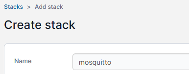
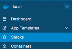
In your Portainer environment (local typically), click on Stacks on the left hand side. Then on the right hand of the page, click on + Add Stack. At the top of the add stack screen you’ll need to give your stack a name. This name will also be prepended to any volumes we create in the stack. I chose mosquitto for my stack name.
Then, you’ll need to paste in a compose file. Here is what I’m using, and what the remainder of the guide will be based upon:
You’ll want to change EST5EDT to a location in your timezone (see this list to get yours). You may also want to change the hostname, Personally, I have not made use of the hostnames. You can remove it entirely for a randomly generated hostname.
In my volumes section, I have mapped localtime. I don’t know that this is necessary (same for the TZ environment variable), but I like to just add them to everything in case something does need it. Frigate, for example, definitely does.
The compose file will create a volume, mosquitto_data, and everything will reside in that volumes root directory (/var/lib/docker/volumes/mosquitto_data/_data).
You’ll want to deploy the stack at this point, and then stop the stack shortly after so we can make a few changes.
Open up a shell, or SSH into your server, and become the root user, either with su if you know your root password, or sudo su.
cd /var/lib/docker/volumes/mosquitto_data/_data
touch passwd
nano -w mosquitto.conf
Please also take note of the touch passwd command in the above snippet. This will create a blank passwd file for us to use in a moment.
I use nano to edit my files, you can use whichever editor you are comfortable with. If you’re in a GUI, I can’t help you. Below are the main changes you’ll need to make. Since /mosquitto/data is mapped to the mosquitto_data volume, there is no need to make any subfolders.
mosquitto.conf:
# if you change the listener, you'll need to change your stack port to match
listener 1883
persistence true
persistence_file mosquitto.db
persistence_location /mosquitto/data

# logging to stderr will show the logs in portainers logs output
log_dest stderr
# you can also log to a file:
log_dest file /mosquitto/log/mosquitto.log
# the types of log entries we will receive:
log_type error
log_type warning
log_type notice
log_type information
log_timestamp true
log_timestamp_format %Y-%m-%dT%H:%M:%S

# do not allow anonymous access to this mqtt server
allow_anonymous false

# the password file for mosquitto mqtt
password_file /mosquitto/data/passwd
After the configuration file is in place, the last step is to add a user for accessing Mosquitto (quick edit: I believe you’ll need to start your mosquitto stack before the below command will work):
Run the above command as sudo, or as a user that is part of the docker group. It will prompt you for a password which is up to you to create. You can replace your_mqtt_username with whatever makes sense to you. For example, my MQTT user is frigate so that Frigate NVR can access the MQTT server as a user named frigate. You may just want to add one generic user instead and use that for all services.
And that’s it! You should now be able to start your Mosquitto stack and the logs should indicate it is listening on port 1883.
2023-08-01T15:29:12: mosquitto version 2.0.15 starting
2023-08-01T15:29:12: Config loaded from /mosquitto/config/mosquitto.conf.
2023-08-01T15:29:12: Opening ipv4 listen socket on port 1883.
2023-08-01T15:29:12: Opening ipv6 listen socket on port 1883.
2023-08-01T15:29:12: mosquitto version 2.0.15 running
Random side note: If you want to install nano inside of the mosquitto container for some reason (docker exec -it mosquitto sh), you’ll need to use the apk command. apk update; apk add nano
But basically it comes down to the below two commands.
The second ‘docker run’ command is what you would use if you have an SSL certificate and key to use. In the second command, I am mapping the local folder /etc/ssl/private to inside the portainer docker container as /certs. So then Portainer can reference the certificates at /certs. You’ll need to change the path to match where you store the certificates.
If you want to install Portainer with SSL support, map your SSL certificate directory (in this example, to /certs) and add the sslcert and sslkey options:
Assuming you have a pool, pfSense, in a mirror of disks ada0p3 and ada1p3. We want to add ada2 as a third disk to the mirror array. By default, pfSense ZFS mirror installation will use p1 (partition 1) for boot and p2 for swap.
gmirror status, zpool list, and zpool status [pool] can be used to help determine names to use below.
First we will clone one of the existing drives partition tables to the new disk:
gpart backup ada0 | gpart restore -F ada2
Then we will use dd to mirror the boot partition:
dd if=/dev/ada0p1 of=/dev/ada2p1 bs=1M
We will use gmirror to clone the swap partition:
gmirror insert swap ada2p1
And for the pool you can either add a spare or an active third disk.
This guide will attempt to help you setup a WireGuard VPN on your pfSense (2.6.0) firewall / router. By the end of this you should be able to connect to your VPN with a mobile device (Android / iPhone) or laptop / PC. This will not walk you through every facet of the install as I am going to assume you know how to install packages and apps.
On your mobile device, you’ll need to install the WireGuard application from the App Store / Play Store. Windows users will need to download the client from the WireGuard website: wireguard.com/install/
And of course, in pfSense, you’ll need to install WireGuard from the package manager.
We’ll get to configuring the clients later and focus on setting up the pfSense side first. As a means of avoiding confusion, I am also going to write the IPv6 setup separately as a lot of users will not need this.
pfSense Configuration
Start by going to VPN -> WireGuard, which should bring you to the Tunnels page. On the right side, click the green “+ Add Tunnel” button.
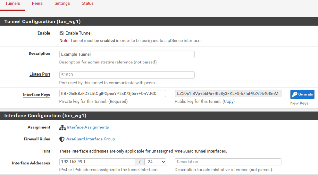
Enable Tunnel: Make sure this is checked. Description: whatever you want, something to identify which clients will be connecting to this tunnel, e.g. Home Tunnel Listen Port: You can change the default if you want, leaving it blank will use the default port of 51820 Interface Keys: Make sure you click the blue Generate button. This will populate the private and public keys.
Do not click Interface Assignments or WireGuard Interface Group until after you have saved the tunnel. It will clear the public key out.
Skip down to Interface Addresses, and assign a new, local IPv4 address, such as 192.168.99.1 / 24. This ‘network’ will be what WireGuard clients use. They will still be able to communicate with your home LAN as long as you permit it in the firewall rules later on. You should have something like this (if this is your first tunnel, it will be tun_wg0 and not tun_wg1, which is fine):
Click on Save Tunnel at the bottom of the screen. Apply changes.
Firewall Rules
Go to Interfaces -> Assignments and add your new tun_wg0 interface from the list of Available network ports. Then go into the interface itself and make sure it is Enabled. I also like to change the name to something like CLIENT_VPN. You do not need to add any firewall rules to this interface. I found if I could use IPv6 without this interface but not IPv4. So I recommend creating it.
Next, go to Firewall -> Rules. You will notice you have 2 interfaces, one called WireGuard and the other called OPT## or whatever you may have renamed it to in the interface settings (e.g. CLIENT_VPN). I have found I do not need any rules under CLIENT_VPN/the OPT interface. Officially it says to add an allow all to any rule but it never generated any traffic, and so I disabled it and have never had any problems.
The main area we want to add rules in is the WireGuard interface. For simplicity, add a new rule in the WireGuard interface to allow all IPv4 traffic, any protocol, any source/destination. For advanced configuration, this is where you will limit which clients can access what. e.g. if you assign a client 192.168.99.5, you can firewall just that IP in here.
Navigate to Firewall -> Rules -> WAN and add a new rule to allow any UDP traffic to 51820 (or your configured port). Instead of a rule, you may need to add a NAT forwarding rule instead, to allow incoming traffic to 51820 (or your configured wireguard port) to forward to the wireguard tunnel IP address (192.168.99.1 for example).
Apply changes.
Configuring Client(s)
First, we need to configure the client, before we can add them to the server. I realize this sounds a little backwards, but clients need to generate their own public key first, which then gets added to the server.
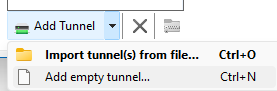
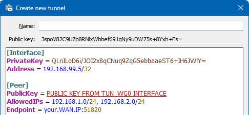
In the Windows client, click on the arrow beside New Tunnel and select Add empty tunnel
Then you’ll need to type some configuration in. The Public-key at the top of this create new tunnel wizard, we will need for later, to add into the Peer section of pfSense. Under the [Peer] section, you will need to use the public key of the tun_wg0 interface in pfSense.
A note on AllowedIPs: If you want to route ALL traffic through your VPN (lan & internet), specify 0.0.0.0/0. If you only want to use your VPN to access your LAN networks, then add your network(s) separated by commas.
I FORGOT SOMETHING IN THIS SCREENSHOT. Under [Interface], add a line called DNS = which should point to your DNS servers you want to use. In order to resolve local hostnames this part is critical. If you’re only doing IP addresses it will be less important. e.g. DNS = 192.168.99.1, 10.1.1.1.
I also just learned you can add DNS search domains to the list, so e.g. DNS = 192.168.99.1, mylan.local and mylan.local will get added to Search Domains.
[Interface] PrivateKey = <automatically generated> DNS = 192.168.99.1 or other DNS IP running on your network. Address = the IP this client is allowed to connect to the VPN with
[Peer] PublicKey = The PUBLIC KEY from the PFSENSE server tunnel AllowedIPs = the list of IPs you want to use this VPN to connect to (e.g. your local networks only, or 0.0.0.0/0 for ALL internet traffic) Endpoint = the public WAN IP address of your pfSense router
Adding Peers to pfSense
The server is now setup, we have our first client configured, and we can begin adding our peers. Navigate to VPN -> WireGuard. Then click on the Peers heading. Then click on the green “+ Add Peer“.
Enable: Make sure this is checked. Tunnel: Select your tunnel interface that we created. Description: A description of who this client is for easy reference. Dynamic Endpoint: Leave this checked. Keep Alive: It seems generally recommended to leave this blank, which is disabled. Public Key:The public key from configuring the client in the previous step.
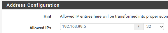
ADDRESS CONFIGURATION / ALLOWED IPs:
A lot of users get confused on this part. Generally one would assume this is where we control what networks the client is allowed to access; but that is actually done from the Firewall rules. THIS section of Allowed IPs is actually ‘which IPs is the client allowed to assign themselves on the VPN tunnel’.
So you need to decide, for every client, what their IP address will be on the VPN. You will almost always want this to be a /32 for an IPv4 and /128 for an IPv6 address. If you do it as a /24 then other clients will not be able to use the address space, and they will be unable to connect to the VPN at the same time.
So, for our first client, let’s do 192.168.99.5 / 32 as that will match what we configured above.
Save peer and apply changes.
Finished!
You should now understand the basics to creating a WireGuard VPN. Primary notes would be that the PUBLIC KEY of the server is used in the PEER section of the CLIENT. The PUBLIC KEY of the CLIENT is used in the peer section of the SERVER. You will never use, nor should you distribute, the private keys. The ones used in this article were temporary only.
You may also want to go to Services -> DNS Resolver and make sure it is listening on your tunnel interface, so you can use it as a DNS server for the VPN clients.
Also note you will not be able to connect to the VPN from the same network that it is running on. Switch to 4G/5G mobile internet and use a hotspot to test or etc.
TODO:
IPv6 is the same as above, but add an additional IP to your tun_wg0 interface (either an fd00 local address, or a fully routable WAN address from your ISP. e.g. my ISP gives me a /56 block, so I use a whole /64 block for my VPN clients). Give them an allowed IP in the peer section, configure the client to also use that IP (Address = 192.168.99.5/32, 1200:1300:1400:1500::1015/128, and also modify AllowedIPs = to include IPv6 address spaces, or ::/0 for all IPv6 routing)
I will work on cleaning up the wording and adding some additional pictures as well. But I really need to get this site migrated to a new server first.